| On-Line User Help Manual | HotFlo! | ||
| This module enables you to analyse the flow of air through the die and predict the amount of porosity that will reside in the casting. It can show the effects of changing the vent sizes and help you decide whether to use natural venting or vacuum assist. |
In order to use this module, you need to have entered the 'Shot Channel Volume' (for hot chamber machines) or 'Shot Sleeve Diameter' (for cold chamber machines) into the 'Data' worksheet, under the section titled 'Machine Data'.
The mass of the parts, overflows, runner and sprue, are shown, as entered in the 'Feasibility' and 'Runners' worksheets. if you have not completed the 'Runners' worksheet, you can enter an estimated runner and sprue mass in the 'Production' worksheet.
DC-CALC converts the mass of each of the die cavity components back into volume in order to establish the total amount of air in the die before you take a shot.
The relevant machine data is displayed. This is the machine chosen in the 'Feasibility' worksheet.
Here you enter the speed of the plunger during the first (slow) phase. This is an important variable, because during this part of the stroke the large amount of air in the machine's shot end must be vented through the die.
Up to a point, the slower the plunger speed here, the more air will be vented. However, this slow speed over the majority of the plunger's stroke will lead to a reduced production rate and a higher part cost. The other limiting factor on horizontal cold chamber machines is the need to keep the speed high enough to prevent air entrapment from waves on the surface of the metal.
You can use DC-CALC to try different values of slow shot speed to establish the best compromise.
The total volume of air (which must be expelled through the vents) which exists in the cavity, runners, sprue, shot sleeve, nozzle or gooseneck is displayed.
This is the challenge for the venting system of the die.
This is where you enter the detailed data about the die venting pathways. This section of the worksheet is to be found to the right of the first data-entry section. If it is not visible on your screen, press 'Tab' or the 'right arrow' until it comes into view.
The air can be expelled from the feed system by several different pathways. It is important to have a basic understanding of them all and how they function.
The first distinction to be made is between vent pathways before the gate and vent pathways after the gate.
This refers to all the vents which connect the runner system to the outside air. It includes the clearance on all ejector pins on runners and sprue posts as well as vents machined into the die parting faces.
Once the metal has reached the runners and gates, these vents no longer function.
This refers to all the vents which connect the cavities and overflows to the outside air. It includes clearance on ejector pins on the cavities and overflows as well as vents machined into the die parting faces.
These vent pathways can operate right up to the point that the cavities and overflows are filled. The important point to realise is that when the 'vents before the gate' have become blocked, the air in the cavities can only be expelled through these 'vents after the gate'.
DC-CALC takes these factors into account when derriving the residual porosity in the part.
The second distinction regards the type of vent, of which there are essentially three kinds:-
1. Ejector Pin Clearance
Ejector pins require a clearance between the hole in the die insert to create a sliding fit. This clearance also creates a pathway through which air can be expelled.
2. Moving Core Slides
Moving core slides also require a clearance for them to function properly, and where this clearance comes into direct contact with a portion of the casting, or feed system, an air vent pathway exists.
3. Parting Face Vents
These are the gaps, either machined or unintentional, which exist at any parting face in the die and connect to any portion of the casting or feed system. Unintentional vents may be created by an inaccurate fit between inserts or by damage to the die faces caused in production.
Identify all circular ejector pins and separate them into those on the feed system (before-the-gate) and those after-the-gate.
Enter a description of each.
Enter the pin diameter for each.
Enter the clearance for each. (This is the clearance between the pin and the hole.)
Enter the quantity of each pin size.
DC-CALC then displays the Vent Area for each pin size, and the total.
'Moving Core Slide' refers only to the situation where the parting plane of the moving core slide comes into direct contact with the metal in the cavity.
'Rectangular Ejectors' include blade ejectors, specially made ejectors and sleeve ejectors (even though they are not rectangular), or any other non-circular ejectors.
Here you enter the Perimeter of the clearance line, the amount of clearance, and the quantity of each.
Identify where you are able to put the parting face vents, and separate them into those before-the-gate and those after-the-gate. For each type enter:-
DC-CALC establishes and displays the total vent area and the areas before and after the gate.
When the data entry of the section is complete, return to the main 'Venting' page to enter the remaining data.
For convenience, the starting point of the plunger is when it is in the fully retracted position. This will then coincide with machine instrumentation readings. All plunger positions are then measured relative to this starting point.
Here you should enter the distance the plunger must travel before the pour hole in a cold chamber machine (or the liner entry ports in a hot chamber machine) are fully closed. You can obtain this data either from the machine manufacturer's drawing or by direct measurement.
During this part of the plunger stroke, no air is being pushed into the cavity or die vents. On a cold chamber machine it simply exits out the pour hole. On a hot chamber machine, any metal under the plunger exits out into the pot and the metal level in the gooseneck does not rise.
For each of the situations above, DC-CALC displays the position of the plunger, measured from the fully retracted position.
Looking at the data above, choose the most appropriate position to change from 1st Stage (slow) to 2nd. Stage (fast) shot speed. It should be just before the metal reaches the gate.
The speed of the air through a long thin vent channel quickly reaches what is known as the 'choked speed' over which it does not increase.
A reasonable value for the vent air velocity would be about 70 meters per second (or 1400 inches per second).
Of course as the cavity fills, some of the vents become blocked and are no longer able to expel air. Here you are asked to estimate a value for this parameter. There is no documented way to do this, but it serves a useful purpose because it makes you think about the possible location of the vents.
You can also experiment with entering different values into this cell and seeing the effect it has on the % porosity. In some instances it has very little impact, in others, significant.
If you have a way to measure the flow rate of air through the vents, you can enter the results here. Most plants do not have access to this data, so the next best thing is to enter the 'Calculated Vent Flow Rates' which is displayed above.
You need to enter a value here because it is used to calculate the Percent Porosity in the casting.
DC-CALC displays the net movement distance, speed and travle time for four different sections of the shot stroke.
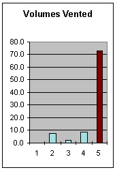
Volume of Air VentedDC-CALC displays a summary of the amount of air vented during various sections of the shot stroke. These relate directly to the information described above, but it is instructive to see where most of the air is expelled. Volume of Air NOT VentedThe volume of air which is not vented ends up in the cavities and overflows as dispersed porosity. This cell quantifies this volume based on all the preceding parameters. |
 |
This is the pressure placed on the metal during the third (intensification) phase. This information comes from the 'Data' worksheet.
It is worthwhile noting that if the gates freeze off before this intensification phase commences, then the full pressure will not be reached in the centre of the casting where any air porosity exists. In these cases, it might be worthwhile to go back to the 'Data' worksheet and reduce the Intensification Ratio, or set it to 1:00 to remove it.
The intensification pressure applied to the casting determines the amount of compression of the porosity.
This is the volume of the unvented air after the above pressure has been applied.
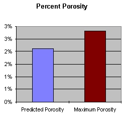
This is expressed as the percentage of the volume above in relation to the casting and overflows.
This is the porosity that would result if there was no venting whatsoever, and all the air in the cavities, runners and shot-end channels ended up in the cavities and overflows.
It is most useful to look at this value in relation to the predicted porosity above, since it will give you a sense of proportion about the effectiveness of your die venting design.
ChartsThe 'Volumes Vented' chart shows the amount of air vented during various sections of the shot stroke:
The 'Percent Porosity' illustrates the parameters described above. |
 |
|