| Software for Die Casting | HotFlo! | ||
To give you an idea of the way that DC-CALC can be used to design and analyse prospective Die Casting dies, a worked example is given here.
|
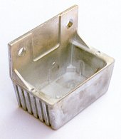
The casting chosen in this example is an electrical enclosure, similar to the one pictured to the right. It is made from Zinc Alloy 3 and weighs 78 grams. It has been proposed that a new version of this casting is to be made with the wall thickness reduced to around 1.5 millimeters. It has been suggested that it be made in a 4 cavity die in an existing 160 ton hot chamber machine. Your task is to evaluate the feasibility of this proposal. |
|
Open DC-CALC and save as a new version with an appropriate name. Some of the cell data is simulated below.
| Description | Electrical Enclosure |
| Machine | 160 ton Die Casting machine |
| Mass | 78 grams |
| No. of Cavities | 4 |
| Wall thickness | 1.5 millimeters |
The only place this die can be satisfactorily gated is along an edge which measures about 50 mm in length. The die operating conditions are now entered.
| Metal Temperature | 410 degrees C |
| Shot Speed Setting | 80% of maximum |
| Die Temperature | 190 degrees C |
| Gate Depth | 0.8 millimeters |
| Gate Length | 50 millimeters |
| Flow Angle | 35 degrees |
Step 2: Examine the output data
A quick glance at the chart shows that things are not looking good. |
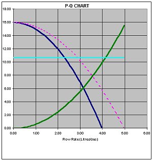 |
The point where the green 'die' line crosses the dark blue 'machine' line is well below the light blue 'maximum power' line. The cavity fill time, at 15 milliseconds is twice as much as the target of 8 milliseconds, resulting in the % of solids in the metal at the point of cavity fill going to 12%, and causing a large amount of cold flow on the surface of the casting. What is more, the gate speed is a low 24 meters per second, well below the target for zinc alloys of around 40 meters per second. Even increasing the shot speed, die temperature or metal temperature will not make sufficient improvement.
At this point you would have to make the recommendation that the proposed machine-die combination is not feasible.
In this example, we also have available another machine, smaller in size, but having a lower cost rate to operate. We can now evaluate how it would perform making the same part, but with fewer cavities.
We only have to change two cells in the worksheet, the machine code, and the number of cavities (we shall choose 2). Instantly DC-CALC displays the new output data and chart, which are simulated below.
Alternative Machine
|
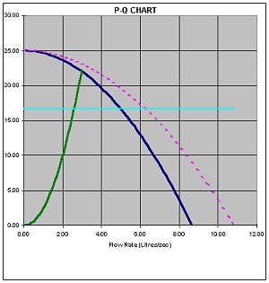 |
The result is quickly seen to be a vast improvement. The crossover point between the green 'die' line and the dark blue 'machine' line is well above the light blue 'maximum power line', meaning that reserve power is available. The cavity fill time meets the target, the % solids is very low, and the gate speed, at 45 m/sec is high enough to disperse porosity.
The total time taken to get to this point is less than 2 minutes!
You could continue to evaluate other alternatives, and then make your final recommendation regarding the machine size and number of cavities for this part. Once the decision is made to proceed, you can use the same file to create the runner design, production and cost data, machine lock-up and tiebar loading, thermal analysis, and die venting as required. The whole analysis could be completed in well under an hour.
|