| On-Line User Help Manual | HotFlo! | ||
| This module is used to calculate the die opening force and the loading on each tiebar. It is particularly useful when the projected area of the part is large and is significantly offset from the centre of the platens. |
The first step is to produce a die layout sketch which shows the location of the cavities and runner system in relation to the centre of the platens. Then you identify the main regions in terms of their projected-area.
A projected-area region is one where the molten metal pressure will create a force against the machine platen lock-up. Therefore any cavity area at the parting faces will project in the direction of the die opening movement. It also includes cavity areas at the parting faces of moving slides. Do not overlook these as their projected area and position in the die can lead to large die-opening forces.
The first task is to give a reference number to each of the Projected Area regions as described above. Go down the worksheet to the box titled 'Keys to Projected Area Regions', and enter a description for each.
When that is done you can specify the size and position of each of these projected-area regions.
You have up to six regions, represented by a number from one to six.
We are looking for a quick result here, rather than decimal point precision, so DC-CALC assumes that each region can be approximated by a rectangle. It requires a size represented in terms of a width and a height.
Most cavities are not simple rectangles, but the human eye is actually quite good at estimating the dimensions of an equivalent rectangle.
For example, a circle of diameter 10 centimeters (4.000") can be estimated as a square of 9 cm x 9cm (3.500" x 3.500").
An irregular shape can be approximated as a series of rectangles.
A runner, if significant in projected-area, can be represented as a long, thin rectangle.
Take a copy of your die layout sketch, and draw these rectangles directly on to it.
Don't forget any moving slide regions which are held shut by the die clamping force. The metal pressure is transferred to the die clamping through the angle plates on the slides.
Enter into this box a description for each of these rectangular regions, up to six. This is purely for narrative information, but it is very useful to have such descriptions if you have to return to the worksheet in the future.
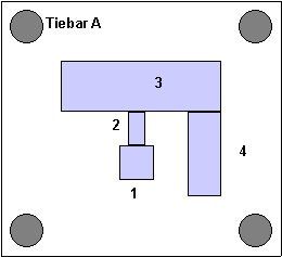
A typical result might look like this:
View towards the moving platen1. Shot sleeve 2. Main Runner 3. Cover Cavity 4. Cover extension, cavity |
 |
The next step is to place a point at the centre of each rectangle. This point represents the equivalent position at which the die opening force from each rectangle, acts upon the platens. It is the distribution of theses points, with the forces proportional to the areas of the rectangles, which determines the load on each tiebar.
Each of these 'points' is then specified in terms of its distance from the centre of the platens - both horizontal and vertical.
|
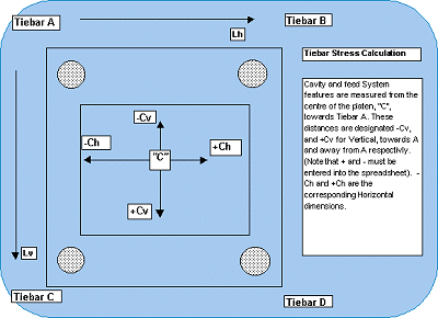
The important concept to understand here, is that the + (plus) and - (minus) directions from the centre, are specified in relation to Tiebar A, drawn here as the upper left hand tiebar. |
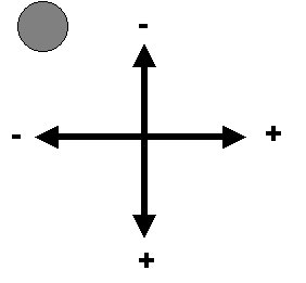 |
To the left (towards A) is negative (-).
To the right (away from A) is positive (+).
For each rectangle, enter into this cell, the - (left) or + (right) horizontal distance from the platen centre to the centre point of each rectangle.
Vertical Distance from CentreUp (towards A) is negative (-). Down (away from A) is positive (+). It might seen a bit counter-intuitive that up is negative, but it is important to enter these direction signs correctly. For each rectangle, enter into this cell the + (down) or - (up) vertical distance from the platen centre to the centre point of each rectangle. |
 |
|
The equivalent projected area of a cavity cut into a moving slide will depend upon the locking wedge angle on the moving slide. Ae=As x tanWa Where:
|
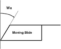 |
If the wedge angle Wa is 45 degrees, then tan(45)=1 and the areas are equivalent.
If the wedge angle is say 30 degrees, then tan(30)=0.577, so the equivalent area is only 58% of the actual area.
Note: For ease of data entry, DC-CALC puts a default angle of 45 degrees in each region. Leave this value at 45, even if there is no moving core, because its effect is to leave the areas equivalent.
Where there is a moving core, modify this value to the actual wedge angle.
DC-CALC calculates the effective projected area of each region based on the data above, and the total.
DC-CALC calculates the force which will try to open the die at the parting line, for each projected-area region, as well as the total.
Each of the values above are intermediate calculations, used to establish the total loading on each Tiebar.
The die opening forces of each region can be combined to establish a single point on the die which gives the equivalent die opening force and Tiebar loading. The Horizontal and Vertical loadcentre coordinates define the position of that single point, relative to the centre of the platen.
The force on each Tiebar is calculated and displayed.
The maximum load on any single Tiebar will determine the required lockup force.
This is 4 times the maximum single Tiebar load, because the machine must put equal force on all 4 Tiebars in order to keep it closed evenly. (Even if your machine has only 2 Tiebars, this calculation still applies since it is in relation to the 4 hypothetical Tiebars A,B,C and D.)
This is the same as the value above, but expressed in Tonnes. Although a "Tonne" is not actually a measure of force but of mass, it is commonly used in the industry.
Note that a metric "Tonne" (1000 kilograms) is virtually the same as a non-metric "Ton" (2240 lbs).
You must ensure that your machine has a Lock-Up safety factor over and above the Die Opening Force.
If you complete a calculation and find that the Die Opening Force is too high, you should first check the value of the 'Intensification Ratio' which has been entered into the Data worksheet for the chosen machine. Since the metal is partially solidified when the full intensification comes on, you can try reducing the ratio to a lower value to see the effect. In other words, although the hydraulic pressure applied to the plunger will be increased by the Intensification Ratio, not all of that pressure will make it to the die faces, due to solidified metal in the cavity and feed system. So the effect of this is to reduce the impact of intensification ratio on die opening force.
Another cause of high Die Opening Force is the Dynamic Pressure Peak. In DC-CALC Version 2.8 and earlier, this dynamic pressure peak was proportional to the square of the speed of the plunger. In Version 2.9 and later, this was changed to be proportional to the speed alone. This was due to new experimental data (see under "Machine and Alloy Data", (Pressure Peak Coefficient) in this manual for more details.
For modern machines with very high plunger speeds, this can have a very large effect on the pressure peak.
If the Die Opening Force seems very low, that can also be a problem. Check if the Dynamic Pressure Peak, at the top right hand part of the page, is zero. If so, you may be understating the die Lock-Up requirements and may need to enter a value for the Pressure Peak Coefficient in the Data worksheet.
These all come from the values entered in the 'Data' worksheet.
This is the length that the Tiebars must stretch in order to equal the die opening force of the metal.
If you are having machine Lock-Up problems, and don't have machine Lock-Up force measuring instruments, you can rig up a dial indicator connected to a long rod between the platens and do a quick check. The Tiebars should stretch greater than this amount to ensure a safety factor over the metal pressure.
If you want to check the Lock-Up using the simple method described above, enter the actual Tiebar length here. Because of different die heights, the actual Tiebar length will vary from the standard (or average) Tiebar length, as entered into the 'Data' worksheet.
You can record the actual measured value here and it will be stored where all the other die-machine combination data is kept. If there is a significant difference, you can go back to the 'Data' worksheet and change this value in the machine, and get DC-CALC to recalculate the expected Tiebar stretch.
Enter the measured value, as described in the two paragraphs above.
Based on the measured Tiebar Length and Stretch, this is actual Locking force of your machine.
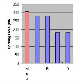
Tiebar Loading ChartThis chart shows you the loading force on each Tiebar caused by the metal pressure during a shot. The 'Maximum' is based on the quoted machine Lock-Up and should well and truly exceed the force on any one Tiebar. |
 |
|