| On-Line User Help Manual | HotFlo! | ||
|
In this module, you develop and specify all the dimensions of the metal feed system to enable the casting to be made with the desired characteristics, to enable the die drawing to clearly detail all the critical dimensions of the gates and runners. |
We start with a blank page, and we need to specify all the dimensions of the total metal feed system from the very end of the runners all the way back to the hot chamber and nozzle or the cold chamber shot sleeve.
The methodology used by DC–CALC starts at the very end of the runner, and works backwards from that point. This is in the opposite direction of the flow of the molten metal, but this important point is the key to the methodology. By starting downstream, we can define the metal speed and direction at each part of the feed system, and thereby create a casting with the required characteristics.
The metal feed system is critical to the Die Casting process, and therefore must be given adequate attention.
However, we also want to get a quick result, so DC–CALC has been designed to make the process as efficient as possible. Firstly, it assumes that you want to make either a single cavity die, or else a die with multiple identical cavities. This means that you only have to specify the gated runners once. All the other gated runners will be identical, and they can be simply joined together with feed runners all the way back to the nozzle or shot sleeve.
If you wish to make a ‘family die’, which has multiple different cavities, you can still use DC–CALC to help with the basic specifications, but the details for each cavity will have to be specified with a manual calculation. In effect, you treat a ‘family’ of parts as if it was a single cavity.
It is useful to think of a Die Casting metal feed system as being constructed of a number of standard 'Building Blocks' which can be joined together to create the total system. At all times, it is important to keep in mind the end result we want to achieve in terms of the casting properties, as well as the physical constraints of a mass of moving metal.
The main buiding blocks are:
Fan Gates
Tapered Tangential Runner Gates
Feed Runners
Sprue runners
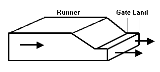
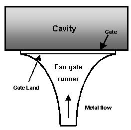
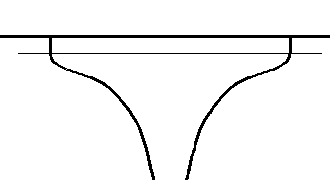
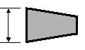
Fan GatesA Fan Gate is created when a feed runner, (either trapezoidal or circular in cross section) is blended smoothly into a thin wide gate into the edge of the casting. To avoid air entrapment and high pressure losses fan gates should be carefully designed so that the cross-sectional area of the runner decreases continuously towards the gate. DC–CALC enables you to quickly design and specify the dimensions of all forms of fan gates. |
 |
In the early days of pressure Die Casting, nearly all castings were made with fan gates of which there are four main forms: -
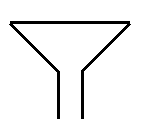
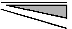
Fan gate with linear widthHere the sides (width) are straight lines from the feed runner to the gate land. To maintain a smooth converging flow path, the depth in the fan gate runner must be machined curved. |
 |
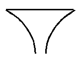
Fan gate with linear depthHere the depth from the feed runner to the gate land proceeds in a straight line (linear) but the sides must be curved to ensure a smoothly varying area. |
 |
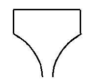
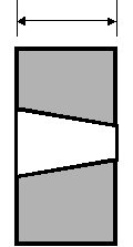
Paddle gateHere a section of the fan gate runner nearest the gate land is made with 'parallel sides'. A paddle gate can be made with either linear width or linear depth. The name derrives from the fact that it looks a little like the shape of a paddle used in a canoe or boat. |
 |
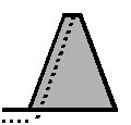
Chisel gateHere the runner and the gate are the same width. The metal flows along the runner, which then steps down through the gate land and the gate, into the cavity. It looks similar to the shape of a woodworking chisel. |
 |
 |
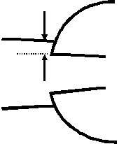
The schematic illustration to the left shows a 'chisel gate'. In this case the runner is trapezoidal in cross section, but it could just as easily be circular. |
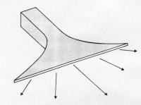
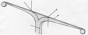
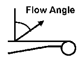
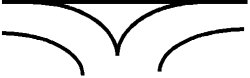
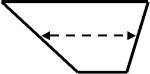
Flow AngleThe Flow Angle is the angle at which the metal flows into the cavity . It is measured relative to a line drawn normal (at a right angle (90 degrees)) to the gate. So with a zero flow angle, the metal flows directly across the cavity from the gate. With a high flow angle, it flows out to the sides. In a fan gate, as illustrated to the right, the metal sprays into the cavity at a range of diverging flow angles, wide at the edges and straight ahead in the middle. |
|
It is also possible to design a fan gate so that nearly all the metal flows into the cavity at a low flow angle by adding a segment of runner near the gate which has parallel sides, a paddle gate.
In seeking a way around the shortcomings of fan gates, the CSIRO Research Team in Melbourne, Australia, developed the Tapered Tangential Runner Gate which has several distinct advantages. See below.
In many dies, the best way of gating the cavity is by using a combination of both gating systems:-
- tapered tangential runner gates for controlled flow angles on long casting edges
- fan gates in short critical regions of the cavity.
See also: Design Details for Fan Gates
|
These are created by making the feed runner branch into one or more tapered runners which travel along an edge of the casting, from which a gate is cut. The flow angle of the metal into the cavity can be precisely controlled by careful specification of the runner dimensions and is invariant to machine settings. |
 |
The elements of a Tapered Tangential Runner System are described below.
|
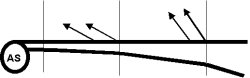
Small circular pockets, which trap a bubble of air in the centre and absorb the pressure shock when the runner system suddenly becomes full. This helps prevent a spurt of metal rushing into the cavity before the main metal stream. |
 |
Shock absorbers are not always necessary, but DC–CALC enables you to specify them in detail. It is a reasonable tactic to design the die to accommodate them, but to perform the first trials without them. If they are found to be required, machine them in at a later time.
This is the small segment of runner, which connects the end of the gated runner to the shock absorber. It is usually not tapered.
This is a tapered tangential runner which has a long thin gate, or a series of short gates leading to the cavity ( known as a "comb gate").
For each cavity, gated runners can have either one branch, or two branches, referred to as Branch A and Branch B.
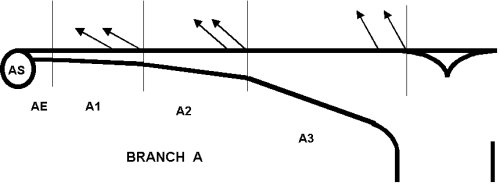 |
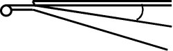
In each gated runner branch, DC–CALC allows you to have up to four different segments, each with a different flow angle into the gate.
Mostly, you would only use one flow angle per cavity, sometimes two, and very rarely would you require four. The sketch above shows one branch of a gated runner with three segments and three different flow angles.
You can define a whole network of feed runners, depending on how many cavities there are in the die, and how they are placed in relationship to the hot chamber nozzle or cold chamber shot sleeve.
|
Feed runners should always be joined with smooth bends to minimise turbulence and pressure losses. The sketches here are included to illustrate the many different ways in which feed runners can be combined: branches of 2, branches of 3, branches of 5, or no branches at all. |
 |
In any die you can define up to eight different sized feed runners, but you can have any number of each size. This leads to a very large number of combinations.
The metal feed system should be designed so that the total area of the feed system decreases as the metal moves from the nozzle, or shot sleeve, to the gate.
This minimises air entrapment and pressure losses and will increase your probability of making a high quality casting.
Since DC–CALC starts at the end of the runner and works backwards in this design procedure, we ensure that the metal feed system area always increases towards the source.
To simplify the process of specifying the total feed system, DC–CALC establishes two key parameters for each runner – the Exit area and the Entry area. (Since we are working backwards from the end of the runner, we always start at the Exit!).
 |
Runners are joined together observing 3 simple rules:-
DC–CALC expects the runner shape to be one of two kinds – 'Trapezoidal' or 'Circular' (T or C). See: 'Circular versus Trapezoidal Runners'
Once you specify the shape, DC–CALC quickly calculates the dimensions. For Trapezoidal Shapes, you enter a depth and it will calculate the width so as to equal the required Area. For Circular Shapes, it will calculate the diameter.
See also: Introduction to Fan Gates
Fan Gate IdentifierYou can define up to 4 different Fan-gate sizes per cavity. Identify each size/type with your own description, number, letter or location. The illustration to the right shows the main sections of a fan-gate runner. The gate land is usually from 1 to 3 mm wide. (0.040" to 0.120"). In this example the is no "parallel" side to the runner just before the gate land, so the flow angle into the cavity will be greater at the edges. |
 |
|
The Fan-gate shown on the right has a short section where the sides of the runner are "parallel" just before they connect to the gate land. This has the effect of forcing the metal to flow into the cavity at a right angle to the gate. ie a zero flow angle. The length of parallel runner needs to be proportional to the width of the gate. |
 |
For each identified Fan-gate, you can have as many as required feeding into the cavity. A typical example is to have say 10 small chisel gates feeding into the edge of a casting to achieve a zero flow angle. Alternatively, two small fan gates might feed into a thick wall section. Yet again, one small fan gate might be used into the 'delta region' between two tangential runner gates.
This refers to the percent increase in the runner, from the 'parallel' section (if any) to the entry to the Fan-gate runner. Because you have to force the high speed molten metal stream to change from the direction along the feed runner out to each side at the same time squeezing down in thickness, you need to allow a generous percentage of taper. A typical amount would be 50%, but 100% is quite common. The larger the amont of taper, the lower the pressure losses, the greater the speed of metal through the gate and the less air will be mixed into the metal stream.
|
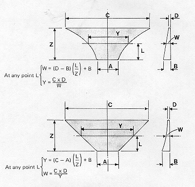
To ensure a smooth flow of metal without air entrapment, the Fan-gate runner must increase in area away from the gate. If you make the Depth a straight line (Linear) as in the top illustration right, the sides (Width) will be curved. Conversely, if the Width is linear, the depth will be curved. It is more common for the Depth to be chosen as linear. The equations for all dimensions are shown in the illustration. DC-CALC automatically calculates all these runner dimensions for you. |
 |
In this section of the worksheet, you need to enter a few basic dimensions so that DC-CALC can complete all the dimensional specifications. All 'Distances' are measured from the gate. Enter the Width of the gate and the Depth of the gate.
At the entry to the gate land, the width is always the same as the gate width, but the depth is usually greater to create a smooth entry. A depth increase from 20% to 50% is quite common. The 'Distance from the gate' defines the gate land, and 1 to 3 mm is quite common (0.040" to 0.120").
At the entry to the parallel section, you need to define the distance from the gate where the parallel section begins. For example, if the gate land was 1.5mm (0.060")and the parallel section was 5mm (0.200") then the 'Dist. from gate' would be 6.5mm (0.260"). You must also define the Depth, which would usually be greater than the depth at the entry to the gate land.
At the entry to the Fan-gate runner, you define the distance to the gate and the Width of the feed runner at this point. Have a look at the calculated Depth of the runner at this point. Make sure it is not too shallow (high heat losses) or too deep in relation to the width (extraction or ejection problems). A ratio of 1 to 1 is a good target. Change the Width until the calculated Depth is appropriate.
DC-CALC displays the mass of the identified Fan-gate runner, both individually and for the total if there are multiple runners per cavity.
For a Fan-gate, the runner usually is at a right angle to the gate (90 degrees). If you require the runner to be at some angle other than 90 degrees, specify it here. This will have the effect of changing the average Flow Angle of the metal into the cavity. For example, if the runner is at 80 degrees (or equivalently 100 degrees) then the effect on the flow angle will be to increase it by 10 degrees.
DC-CALC displays both the estimated average flow angle from the Fan-gate and the total flow angle including the effect of an angled runner. Also displayed is the actual gate area and the effective gate angle due to the flow angle.
The definition of all Fan-gate dimensions are illustrated below.
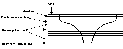 |
At the Runner Points 1 to 9, DC-CALC displays the Width, Depth and 'Dist. from gate' which is required to create a smooth runner with the taper specified above. These dimensions must be added to the tool drawing so that the toolmaker can create a Fan-gate which will achieve the metal flow characteristics required for a high quality casting.
This section is where you specify all the dimensions for tapered tangential runner gates. For a description of the methodology and definitions of relevent feed system building blocks, see Introduction to Tapered Runner Gates.
A code is assigned to each part of the feed system to help you identify it in other parts of the worksheet.
| Defined Runner Elements | Branch A | Branch B |
|
Shock Absorber Runner Extension Gated Runner, Segment 1 Gated Runner, Segment 2 Gated Runner, Segment 3 Gated Runner, Segment 4 |
AS AE A1 A2 A3 A4 |
BS BE B1 B2 B3 B4 |
|
You need to specify either Y, Yes or N, No. See "Shock Absorbers".
If you enter N for No, no text will appear in the lines below. If you enter Y for Yes, you will see additional text as described below.
Enter 'T' if you wish to use a Trapezoidal shaped extension runner and ‘C’ for Circular.
See definition of "Runner Extension" above.
See: "Circular versus Trapezoidal Runners"
Enter all other data regarding the Shock Absorbers, as requested in the text, using the units of measure indicated.
Shock Absorber Diameter is the diameter cut into the face of the die, typically 10 to 20 mm (0.400" to 0.750").
Shock Absorber Depth is the depth into the die, typically 3 to 10 mm (0.120" to 0.400").
Runner Width and Runner Depth or Runner Diameter, refer to the dimensions of the Runner Extension.
Runner Extension Length is the distance from the end of the gate to the entry to the shock absorber.
Runner Area is the calculated cross sectional area of the Runner Extension.
Mass shows the calculated metal mass contained in each shock absorber, runner extension and the total. Keeping this value as small as possible will minimise metal and energy waste.
See definitions: "Gated Runner"
'T'=Trapezoidal, 'C'=Circular
See: "Circular versus Trapezoidal Runners"
You can define up to 4 segments in each gated runner branch. DC-CALC requires you to define each gated runner segment measured from the same starting point 0, called the ‘Gate End’.
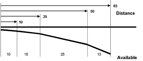 |
For example, the data for the runner sketched above (in millimeters) is:-
| Segment | A1 | A2 | A3 | A4 |
| Distance from Gate-End to end of segment | 10 | 25 | 50 | 63 |
DC-CALC calculates the length, within this segment, that is available to have a gate cut. There will be some dies where you may want to cut a gate channel in only part of the available runner length. This is known as a ‘comb gate'. You would use this when the depth of the gate becomes so small that atomisation of the metal does not take place and unsatisfactory filling results.Use the Feasibility worksheet of DC-CALC to determine if atomised flow will occur.
If you want to use a comb gate in any segment, these two cells are how you specify this to DC-CALC.
For a normal, fully gated runner you would enter 1 for the 'Number of Gate Channels' and set the length to the total available gate length for the segment. For Example, you might want to cut a comb gate in segment A3, and could enter
No. of Gate Channels 4
Length of Each Gate Channel 3mm (0.120")
Enter the depth of the gate, in each segment. Here you could choose different depths in each segment if you require.
Note that if you want to cut the gate into each die half, you should enter here the sum of the gate depths in both die halves.
Desired Flow Angle from the GateThe Flow Angle is measured from a line at 90 degrees to the gate. Be aware of this, because if you measure it from the gate you will end up with incorrect results. The flow angle of the metal is one of the most important elements of high pressure Die Casting die design. It is effected by the gate area and the runner area. |
 |
|
The ability to specify the Flow Angle is a most important design tool. A low flow angle (say 30° -35° ) will direct more of the metal stream to the centre of the casting. A high Flow Angle (say 35° -45° ) will direct more to the end of the casting. |
 |
You can specify a different Flow Angle for each segment if you wish. This is illustrated on the diagram above. The segment nearer the shock absorber is using a higher flow angle than the segment closer to the feed runner.
It is a good idea to draw a sketch of the cavity and the gate and add arrows to indicate the metal flow at the required Flow Angle for each segment.
It is not necessary for the runner to be a straight line. It should follow the contour of the edge of the casting.
To the far right of this line on the worksheet, after the last data input cell for Segment B4, are two data display cells ‘Average’ Flow Angle and ‘Target Flow Angle’.
The ‘Target’ Flow Angle is the value you entered into the 'Feasibility' worksheet. Because Flow Angle reduces the effective gate area, it has an effect on the ability of the machine to fill the cavity.
The ‘Average’ Flow Angle, is calculated from the various Flow Angles you enter into segments A1 to B4. If you find that the average is not the same as the Target, you should go back to the 'Feasibility' worksheet, enter the new Average Flow Angle into the appropriate cell and double check that the fill time and gate velocity are still acceptable.
This data is the net result of all the data you have entered in the 'Gated Runner Data' section so far.
Whether you have designed a continuous gated runner, a comb gate, a single segment or 8 segments, a common Flow Angle or 8 different Flow Angles, the net results these will have on the actual and effective gate areas are displayed here.
The last column ‘Target’ comes from the 'Feasibility' worksheet and if your Total Area (in the second last column) is significantly different to the ‘Target’, you should return to the Feasibility Worksheet and change the gate depth or length so that it equals the Total.
This is part of the design feedback loop, which is required to refine your parameters.
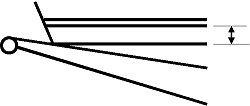
This is the width of the small parallel cross section through the gate. It represents the separation of the cavity from the Runner or the ‘Delta’ zone.
The runner dimensions must be specified at the end of the gate since this is the starting point for the calculations. Keep these dimensions as small as possible to reduce runner mass. If Shock Absorbers have already been specified, then these dimensions should be set to the same dimensions of the Runner Extension. (See under: Shock Absorbers).
For Circular Runners, this cell should be set to the same value of the cell above to avoid possible problems with self-referencing equations.
|
This allows for the possibility that you might not want to have the runner parallel to the gate, but approaching at an angle. |
 |
One reason you might consider designing such a feature is to assist in reducing the Flow Angle.
To get a very low Flow Angle (say 20° ), and to avoid the runners becoming excessively large in area (and therefore mass), having the runner at an angle to the gate will help. The runner is joined to the gate through a thin region called a ‘delta’ region.
For normal runners which are parallel to the gate, this would be set to zero.
|
But for Runners at an Angle to the gate, as described above, you have the option to have the exit (end) of the runner some distance from the land which may help in placement of runner extensions and shock absorbers. |
|
DC-CALC will calculate and display the distance of the runner from the land at subsequent segments (Entry points).
This calculation is only used for Runners at an Angle to the Gate (described above), in order to calculate the runner mass accurately.
|
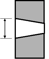
At any segment where the Runner diverges from the Gate land, you make a thin channel between them, and this is referred to as a ‘Delta’ region. Typically it occurs in the small triangular space where two tapered tangential runners diverge. |
 |
 |
However, it is also required when you design a runner to be cut at an ‘Angle to the Gate’, as shown to the left. |
If you have a Delta region in your design enter its average depth into this cell, in millimetres. It is usual to cut the Delta region so it tapers slightly, decreasing in cross section towards the gate.
For Circular Runners, this cell should be set to the same value of the cell below to avoid possible problems with self-referencing equations.
For Trapezoidal Shaped Runners, enter the preferred depth of the runner at the Entry of each segment.
For Trapezoidal Runners, DC-CALC will display the required width of the runner at the Entry of each segment.
If the width is not practical, change the depth, above, until you obtain a satisfactory result.
With trapezoidal runners, by definition, their 'width' varies with depth. So, as standard practice, it is always specified at the halfway depth position. The width will be greater above this point, and smaller by exactly the same amount below it. For this reason we can still multiply the width (at half depth) by the depth to get the cross sectional area of a trapezoidal runner.
For Circular Runners, DC-CALC will display the required diameter at the Entry to each segment.
This is the calculated angle between the two side walls of the runner, created by the tapering of the runner.
This is the area at the Entry of each runner segment, it is used in the Feed Runner design, described below.
DC-CALC calculates the mass of the runner and delta zone to help you assess the amount of wasted material you are designing.
By definition, a feed runner does not have a gate. Here you create and enter information about the feed runner in the die, be it a simple, single feed runner or a whole network of different sized runners. They are designated FR1, FR2, FR3.....
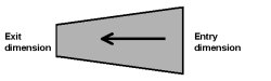
A feed runner can be straight or curved, but DC-CALC is only concerned with the dimensions at the Exit and Entry.
Enter 'T' for Trapezoidal and 'C' for circular.
Because there are so many different ways you can join a network of feed runners, the data entry into these cells is designed to allow you many possibilities.
The data in this cell tells DC-CALC the Exit Area of the feed runner, as a formula which relates to other downstream runners.
The Exit Area of a feed runner is the sum of the Areas of the downstream Runners it has to feed.
You can have up to 8 different sized feed runners, but you can have as many of each size as you require.
Step 1 : Join a Fan-gate Runner or Gated Runner to a Feed Runner.
The Feed Runner FR1 (or Sprue Runner) needs to have its Exit Area set to the same, as, or greater than, the area of the Fan-gate Runner, Gated Runner, or othe Feed Runners, that it feeds.
Look at the row ‘Runner Entry Area’ in the Gated Runner Data Section above.
Select the last segment of Gated Runner Branch A, which has a non-zero 'Runner Entry Area' displayed. Note its Column Letter Header at the top of the screen, and its Row Number at the left edge of the screen.
(For example, if there is only one segment in the gated runner, A1, and its Column is D and its row is 118, its cell reference is D118).
=(Area of Last Segment of Branch A) +
(Area of Last Segment of Branch B)
Examples:
=D118 + H118 (or D214 + H214)
=E118 + J118 (or E214 + J214)
=(E118 + J118) x 1.05
This last example says that the Exit Area equals (the Entry Area E118 plus the Entry Area J118) plus 5%.
Step 2 Join the Feed Runners Together
If for example, two feed runners branch from one larger feed runner which leads to the metal source, use the same cell formula technique, described above, to combine the Exit and Entry areas. If there are two identical runners joining to a single upstream feed runner, then you must specify that in the Cell formula. For example=2*E118
Continue this process until you arrive back at the hot chamber sprue or the cold chamber shot sleeve.
As a quick reference, the Exit Areas for the various Runner types in DC-CALC Version 2.8, can be found at the Rows and Columns listed below:
| Metric Version |
Non-Metric Version |
Multi-Lingual Version |
|
| Fan-gate Runners | F30 or L30 F54 or L54 |
F30 or L30 F54 or L54 |
F52 or L52 F97 or L97 |
| Tapered tangential Runners | Row 118, D to K | Row 118, D to K | Row 214, D to K |
| Feed Runners | Row 138, D to K | Row 138, D to K | Row 244, D to K |
This is the % change in the area of the feed runner, along its length, which is necessary to create a fully tapered runner system to minimise pressure losses and entrapped air in the molten metal.
Because the DC-CALC process starts at the gate and works BACKWARDS, the taper in any length of feed runner makes the Entry larger than the Exit by the % entered into this cell.
Enter the length of this Feed Runner.
Because you can have multiple (identical) cavities in the die, and different ways of joining up the Feed Runners, here you enter the total number of each identical feed runner in the die. This data is used to calculate the mass of the runner system you are designing. It is not used to calculate the exit area of the feed runners. You have to do that by entering it into the Cell formula for the runner area.
Based on the above input data, DC-CALC will display the calculated dimensions, and area, for the Entry of each Feed Runner, and its mass.
Enter this section only if you are designing a feed system for a traditional Hot Chamber machine, where the molten metal comes through a sprue hole in the back of the die.
If it is a multi-slide machine with the metal injected into the parting line of the die, you can specify all elements as Feed Runners in the section above.
‘H’ refers to the HotFlo! hot sprue system. ‘C’ refers to a traditional cold sprue with a conical sprue post with runners cut into the sides.
This line will appear if you have entered 'H' for Hot Sprue system in the line above.
Here you must enter a spreadsheet cell formula similar to the way described in Runner Exit Area (Cell formula) above.
Enter a formula to relate the area of the appropriate Feed Runners (FR1, FR2, .....FR8) to the HotFlo! sprue exit.
For example, if you were proposing to use a HotFlo! sprue with a Mono Tip Style (single runner outlet), and you wanted to connect it to Feed Runner FR4, you would enter :
=G81
where G81 is the spreadsheet cell reference for the Entry Area of FR4.
If you are using a Duo Tip Style (two runner outlets), you need to be aware that the Runner Entry Area of the Feed Runners FR1, FR2,.... is, in each case the area of a single runner. Therefore you may need to enter a factor in the cell formula to specify the correct runner area.
For example, if you were connecting to two identical copies of Feed Runner FR4, you would enter :
=2*G81
DC-CALC arrives at this suggestion using the data you entered in the 'Feasibility' worksheet. Is based on the rule of thumb that the sprue area usually needs to be twice the gate area. It does so in order to arrive at a quick feasibility suggestion of the HotFlo! Series you are likely to require, without doing the full runner design. However, once you reach this point in DC-CALC, you have now specified the runner system in detail. You now need to review the rule of thumb suggestion to see if it is satisfactory.
Is the 'Hot Sprue Exit Area' less than or equal to the area of the 'Suggested Series from Feasibility Analysis' ?
If not, you can either choose a larger HotFlo! sprue kit ( see below), or revise your runner design to make it smaller.
Revising the runner design means going back over some of the assumptions you made along the way. You can change them in DC-CALC to see how much effect they will have on the sprue area. (Remember to make a copy of the DC-CALC file, or take a note of the values before you change them.) Some of the data you should review is :
Flow Angle : a greater Flow Angle will reduce runner and sprue size.
Taper : by reducing the amount of taper in the feed runners, it will decrease the required sprue area.
Number of Cavities : Less cavities require a smaller sprue area.
If the area of the 'Suggested Series from Feasibility Analysis' is smaller than the 'Hot Sprue Exit Area' (above), and you have reviewed the runner design as described in the paragraph above, without success, then you can specify here a HotFlo! Series with a larger exit area.
If the area of the suggested Series is adequate, enter the suggested Series number.
This appears if you specified 'C' in 'Select Hot Sprue or Cold Sprue' above.
A cold sprue means that the metal in the sprue hole will solidifiy and must be extracted with each shot. The lines below will appear in DC-CALC to enable you to fully design and specify the cold sprue system. It will also calculate the mass of metal in the sprue system to enable you to judge the savings that could be made by going to a HotFlo! sprue system.
|
A Sprue Runner is cut into the sprue post (and sometimes the sprue bush also) to create a runner channel to join with the feed runners at the die face. DC-CALC allows you to design a traditional cold sprue with up to four Sprue Runners, designated SR1, SR2, SR3 and SR4. |
 |
This is only required if you are designing a traditional cold sprue with runners cut into the sprue post.
Enter ‘T’ for Trapezoidal shape sprue runners or ‘C’ for Circular.
Similar to the technique in ‘Feed Runners’ above, enter the formula for the sum of the Feed Runner Areas to which each Sprue Runner will join.
How much larger, entered as a %, will the entry to each Sprue Runner be, compared to its exit.
You have the option to create more than one copy of each Sprue Runner SR1, SR2, SR3, SR4. For example, a sprue post with 2 identical sprue runners cut into each side could be designed as SR1, with 2 copies, to speed up the data entry.
Enter the width of each Sprue Runner at its exit and entry. This gives you the option to taper the width of the sprue runner to match the conical shape of the sprue post. If you make it thinner at the top, it will also be deeper at the top, and vice versa. DC-CALC displays the depths under ‘Runner Dimensions in Sprue Post’ described below.
Sprue Hole Diameter at BaseThe diameter of the sprue hole in the fixed die half, at the parting line. |
 |
Sprue Post Diameter at BaseThe diameter of the sprue post at the parting line. |
 |
It must be smaller than the sprue hole at the parting line, and usually it is made at least 1mm (0.040") smaller to create a thin conical shell of die cast metal around the post. Whilst this conical shell of material is not desirable from a metal flow point of view, it provides mechanical strength to the solidified sprue on ejection.
DC-CALC assumes you will create a constant clearance between the sprue hole and post, and displays it here.
Sprue Hole LengthHere you enter the length of the sprue hole from the parting line to the nozzle seat. Usually it will be the same, or very similar to the thickness of the fixed die. This data is used to calculate the mass of the sprue. |
 |
Nozzle Bore Location ClearanceTo allow for some possible misalignment between the machine nozzle bore and the sprue hole, the hole in the nozzle is usually made smaller. This ensures that the ‘pip’ on the end of the sprue will part cleanly on die opening. This is where you specify the amount of that clearance. Enter the required amount of clearance on each side of the nozzle. If you enter 1mm (0.040") clearance, the sprue hole will be made 2mm (0.080") greater in diameter. |
 |
Note: For dies with a HotFlo!hot sprue system installed, this requirement is not required, and the bore in the nozzle is made the same size as the sprue entry hole.
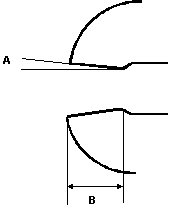
Reverse Draft Angle in Nozzle BoreA small reverse taper is usually machined into the bore in the nozzle, right at the tip, illustrated as Angle A on the sketch to the right. Although undesirable from a metal flow point of view (because it creates an expanding flow path with high turbulence), it is usually required so that the ‘pip’ of solidified metal at the tip does not snap off and block the nozzle, but is extracted cleanly with the sprue. This data is used to calculate the required sprue hole diameter. Here you specify the angle per side, in degrees. A 1° angle entered here will result in a 2° included angle. Internal Land in Nozzle BoreThis dimension refers to the length of the reverse draft angle in the nozzle bore described above, before it opens out into the main nozzle bore. It is shown as dimension B on the sketch to the right. Enter the value. |
 |
DC-CALC uses this dimension to calculate the minor diameter you will require to machine in the nozzle tip before adding the reverse taper. This will ensure that the point of greatest restriction in the nozzle will be large enough to feed the runner system you have just designed.
Much of the data required for the sprue and nozzle tip design are rather tedious to have to specify, but if you do not do so, you run the risk of inadvertently ending up with a constricting condition in the nozzle.
This is quite often the cause of inadequate or inconsistent casting quality. Of course, you could consider eliminating all these sprue-nozzle restrictions altogether by specifying a HotFlo! hot sprue system.
DC-CALC displays all the data regarding the Sprue Runners SR1, SR2, SR3, SR4.
Note 1: The ‘Depth’ refers to the depth that the runner must be machined into the post itself. The actual depth of the flow path, as experienced by the flowing metal, is greater than this by the amount of the ‘Clearance: Sprue Hole to Post’. See above.
|
Note 2: ‘Width at ½ depth’ refers to the fact that Trapezoidal runners have tapered sides, (often with different angles on each side), and so their width must always be measured at the position of half the depth. |
 |
DC-CALC displays the diameter you will have to machine at the point of the nozzle seat in order to satisfy –
This is the hole you have to drill in the nozzle before machining the reverse taper angle. See ‘Internal Land in Nozzle Bore’.
DC-CALC calculates the draft angle of the sprue hole as a result of the previously specified Exit and Entry diameters and length.
DC-CALC displays the mass of the runners cut into the sprue post.
The mass of the conical shell which results from the clearance between the sprue post and sprue hole.
DC-CALCdisplays the total mass of the sprue and runner mass that you have just designed, including:
Shock absorbers
Gated Runners
Feed Runners
Sprue Runners
Sprue Cone
If you think there is too much wasted metal in the sprue and runners compared to the part weight, you should consider redesigning it using a HotFlo! hot sprue system.
For Cold Chamber machines, enter the desired final length of the solidified biscuit in the end of the shot sleeve.
DC-CALC will then display the Biscuit Mass and the Total Runner and Biscuit Mass of the designed feed system.
The last part of the worksheet contains a summary of all the important aspects of the gating and runner system that you have just finished designing. You can print out these next few pages, and, combined with a few sketches, they can be used to complete the detailed drawing of the die.
|