| On-Line User Help Manual | HotFlo! | ||
OverviewThis is the starting point for every new Die Cast part analysis and its main purpose is to establish the best die-machine combination, the number of cavities, the overall gate length and depth and the required operating conditions to make the part to the specified standards - temperatures, shot speed settings and fill conditions. |
Before commencing the Feasibility Analysis, ensure that the Die Casting machine data for all machines in your plant have been entered into the Data section of the spreadsheet which you access via the tab at the very bottom of your screen.
If the 'Data' tab is not visible, click the rightmost tab until it scrolls into view.
You create a new DC-CALC file for each Die Cast part.
Open your master copy of DC-CALC, which contains all your machine and alloy data and think of a new name to to call this new copy; something related to the part such as; part number, name or enquiry number for a quote.
Then select 'File', 'Save As' and give it the new name.
Data InputProduct Descriptive TextThe top sections are for purely descriptive text to help you identify the product, customer, part number and the like. They are all optional, however some of these fields will appear on other DC-CALC sheets so it is a good idea to enter meaningful text. It is a good idea to enter the new file name so that it will appear on printouts and enable you to quickly recall it in the future. Always enter the data in the cell on the lefthand side. |
 |
|
Here you enter the Code for the alloy you wish to use, as listed in the the Alloy Data table in the Data worksheet. To see the Alloy Codes already entered, go to the bottom of the screen and select the Data worksheet. (It might be hidden from view to the right, so click on the rightmost tab until it scrolls into view)
You can easily compare the relative advantages of making the part from a different alloy by simply changing the code in this cell. All related variables, including the product costing, will be altered accordingly. If you wish to compare alloys with significantly different densities (Al versus Mg for example), then you should enter the size of the casting as a Volume rather than a Mass. See 'Enter Mass or Volume'.
Here you enter the Code for the Die Casting machine you wish to consider for production of this part. The Machine Code, and its associated data needs to have been previously set up in the Data worksheet. To see which machines have had their data entered into the DC-CALC Data worksheet, go to the bottom of the screen and select the Tab titled 'Data'. (It might be hidden from view to the right, so click on the rightmost tab until it scrolls into view).
You can easily re-evaluate your designs on different machines by changing this cell. Note that every plunger-machine combination requires a different Machine Code.
See: Pre-Requisties.
Here it is asking you if you wish to specify the Mass or the Volume of the part.
Usually you will enter M for Mass.
However, if you wish to compare the design calculations between different metal alloys, Aluminum versus Magnesium for instance, then it is much more convenient to enter the Volume. The reason is that the volume of the part remains the same whereas the mass will vary with alloy density. If Volume is entered, you can simply enter a new Alloy Code at any time and DC-CALC will recalculate all the other parameters. If Mass is entered, then when changing alloys, you need to also enter the new Mass each time. Besides being tedious, if you forget to do so, you will introduce errors into your design calculations.
Calculating Casting VolumeIf the part has been designed on a CAD system then most likely you can obtain the Volume of the part directly from the software. Alternatively, you can calculate it manually, although it can be a very tedious process. If you know the mass of the part in a given alloy, use DC-CALC to calculate the volume for you as follows:-
|
The displayed text will change depending on whether you entered 'M' or 'V' in the cell above.
Enter either the Mass or the Volume of the cast part only.
The displayed text will change depending on whether you entered 'M' or 'V' in the cell above.
Enter either the Mass or the Volume of the Overflows only.
Overflow material is any metal which passes through the gates, through the cavity of the casting and out into 'overflow' pockets cut into the die, slides or shortened ejector pins. It does not include metal in the sprues and runners.
Because all 'Overflow' metal must pass through the gate, it increases the calculated 'cavity fill time'. This is a good reason to keep all overflows as small as possible. Better still, leave them out completely if you can. (See 'Frequently Asked Questions')
If the die contains a single cavity producing one Die Cast part per shot then the number of cavities is 1.
If it contains 2 cavities of the same part, then the number of cavities is 2, and so on.
However, in the case of a 'family die', the data which must be entered into this cell is not quite so straightforward.
A 'family die' is one which produces several different parts at the same time in the same die. It has more than one cavity, but they are not identical cavities. Because of the way DC-CALC uses the data in the 'No. of Cavities' cell, you have to treat the family of parts as if it is a single cavity.
Say you want to make the following three parts in one shot in the same die.
|
In this case, you would enter:
No. of Cavities=1
Estimated Mass=180 grams
However, if you wish to make two of each part, (ie. in a die with 6 different cavities), then you would enter:
No. of Cavities=2
Estimated Mass=180 grams. (Remains the same)
The purpose of entering the Wall Thickness of the part is so that DC-CALC can calculate the 'Target Cavity Fill Time'.
You should select and measure the minimum wall section of the part in the most critical segment of the casting. If there is a segment which requires a high quality surface finish then use the average or minimum wall section in that segment.
Always try to place the gate into the section of the casting with the smallest Wall Thickness. This will ensure that the molten metal passes through the thin section on its way to the other parts of the cavity, and, in so doing, add heat to the die at that point, improving surface quality and die filling.
As the molten metal stream travels through the sprue, runner and cavity, some particles will give up sufficient heat to become solidified. The 'Percent Solids' then, is the percentage of the metal particles which have solidified during the cavity filling phase.
It is important to realise that all castings have some percentage of solids. Furthermore, the the cavity can still continue to fill even if the metal stream contains up to about 40% solids. Higher percentages than that will usually result in 'short shots', that is, incomplete cavity fill.
These solidified particles are the cause of 'cold flow' effects on the surface of the casting. Consequently, if you are designing a die for a thin walled zinc casting which requires a first class surface finish for electroplating, then the 'Target Percent Solids' would need to be very low. (See the section below under 'Target Percent Cold Flow'.
On the other hand, if you are designing a die for a thick walled casting in say aluminum, and you are concerned about eliminating internal shrinkage voids (which can lead to 'leakers' in gas tight products), then you would target a higher percentage of solids, say 20%. Since shrinkage voids are caused by metal in the centre of the casting remaining molten well after the gates are frozen off and can no longer be fed with molten metal as it shrinks, increasing the Percent Solids reduces the amount of molten metal left at cavity fill. This is more applicable to Aluminum alloys and those with a greater solidification temperature range.
This is based on the empirical observation that the percentage of the casting surface area that contains cold flow is related to the calculated percentage of solids in the casting by a factor of about 2.
So, a casting with 5% solids at the point of cavity fill will have cold flow marks on about 10% of its surface area.
That may still result in an acceptable casting if it appeared on a non-visible segment.
When designing the die for the casting you need to be well aware of the application and critical features which will be required in the finished product.
You cannot enter a value for 'Target Percent Cold Flow" directly, but adjust it through the 'Target Percent Solids' cell above.
Here you enter the temperature of the metal when it is forced into the cavity, in Degrees Centigrade.
You use this cell to simulate the opening and closing of the second stage shot speed valve on the machine.
The maximum second stage plunger speed (100%), is determined by the size and efficiency of the piping, ports and valves in the hydraulic system. By turning down the fast (second stage) shot speed valve, the plunger speed is reduced from the maximum.
So, half speed is simulated by entering 50% into this cell.
The effect can be seen in the 'Set Plunger Speed' cell, and on the P-Q chart, by the position of the Actual Machine Performance curve (dark blue line).
Note: The 'Slow Shot Speed' is used to allow air to vent from the die during the first stage of the plunger stroke. DC-CALC deals with the setting of the 'Slow Shot Speed' and the point of changeover to 'Fast Shot Speed' in the Venting worksheet.
Into this cell, you input the average die surface temperature you expect to use to produce this part.
You must enter some value here for the equations in other cells to work so enter your best estimate to start. You can always return to it later and adjust the value to get the casting quality result you require.
This is simulating what the Die Casting machine operator does by running the die at a range of temperatures to find the best results.
Enter the depth of the gate.
If you intend to have different gate depths in different segments of the casting, you should take the average depth. This part of DC-CALC is used only to determine the feasibility of the die-machine combination. The detailed gate dimensions in each part of the runner are established and entered in the 'Runners' sheet , and this is where different gate depths can be specified.
Enter the gate length of a single cavity.
So, if you are planning a die with four identical cavities, and each cavity will have a gate length of 60mm (2.360"), then you enter 60 (2.360) in this cell. DC-CALC will calculate the Total Gate Area as=(Depth x Length x No. of Cavities).
If you discover, through using DC-CALC, that you will not be able to make four of these parts to a satisfactory quality on the planned machine, and instead opt for a two cavity die, then, by simply changing the data in the 'No. of Cavities' cell, DC-CALC will immediately adjust the Total Gate Area and all other dependent variables.
Note that if you are designing a multi-cavity family die, you need to treat the family of parts as a single 'cavity'. See also under 'No. of Cavities' above for a further description of the treatment of family dies.
Here you enter the desired average Flow Angle of the metal into the cavity, in degrees.
You may want to have different Flow Angles at different points along the runner, but since this worksheet is to establish the overall feasibility of your die design, enter only your best estimate of the average Flow Angle. Detailed Flow Angle design is done in the 'Runners' worksheet.
| The Flow Angle is measured from a line at 90 degrees to the
gate. A low Flow Angle (say 30 to 35 degrees) will direct more flowing metal across the centre of the cavity. A high Flow Angle (say 35 to 45 degrees) will direct more flowing metal to the ends of the cavity. |
 |
The Discharge Coefficient (Cd) represents the loss of efficiency of the total metal flow system compared to the theoretical maximum.
In the 'Data' worksheet we entered a value for the 'Maximum Plunger Speed'. If this value was the dry shot velocity, (that is without a plunger being connected), then a realistic value for Cd is around 0.55. If however, the speed was measured with a plunger connected, and while the metal is passing through a standard nozzle bore, then a value of Cd of around 0.70 should be used.
Why?
In the first instance, the actual plunger speed achieved during cavity fill will be slower than the dry shot speed due to the friction of the plunger rings and resistance pressure from the metal flowing through the gooseneck and nozzle.
In the second instance, these losses have already been accounted for in the lower value of Maximum Plunger Speed.
Of course, the best way to determine Cd is to measure it directly with suitable Die Cast instrumentation. The actual measured value will vary from die to die, but we need to establish a realistic average to enable DC-CALC to be used as a predictive die design tool.
Two input values are allowed here, 'H13' or 'P20'.
H13 is fully through-hardened hot work die steel which is the usual material for Die Casting Dies.
P20 is pre-hardened nitriding steel, normally only used for die blocks (bolsters), but sometimes used for cavity in very small, simple zinc Die Casting dies.
An empirical constant that depends upon a number of factors including the type of die material, the alloy being cast, the condition of the die surface and the release coating. For most situations the values used in DC-CALC will be adequate. For further information see "Gating Die Casting Dies" by E. A. Herman, listed in the references.
Most of the data in this part of DC-CALC comes from the Data worksheet where you enter the basic information about each of the machines in your plant. However the data described below is calculated in the Feasibility worksheet in order to determine the machine-die operating parameters.
This is the maximum metal pressure exerted on the metal by this machine with the nominated plunger diameter. It is the pressure exerted on the metal when the plunger has come to a halt after filling the die (and before any intensification commences).
It is represented on the P-Q chart by the highest pressure point of the Maximum Machine Performance curve (pink dotted line).
Metal speed through the gate is sometimes limited by the maximum metal pressure of the machine. To increase machine metal pressure, you could install a smaller diameter plunger. However this will also decrease the Maximum Flow Rate as described below.
This is the maximum metal flow rate that this machine can achieve with the nominated plunger diameter.
It is represented on the P-Q chart by the by the greatest flow rate point of the Maximum Machine Performance curve (pink dotted line).
To increase the maximum flow rate of a machine you could install a larger diameter plunger. However this will also decrease the Maximum Metal Pressure described above.
When you turn down the shot speed valve on the machine you you reduce the metal flow rate of the machine. This is simulated in DC-CALC by adjusting the 'Fast Shot Speed Setting'.
The results of this are represented on the P-Q chart by the position of the Actual Machine Performance curve (dark blue line) compared to the Maximum (pink dotted line). To test this, make a change to the Fast Shot Speed Setting and see the effect it has on the P-Q chart.
This is the dry shot speed that the plunger will achieve as a result of the value entered in 'Fast Shot Speed Setting'.
Note: The Slow Shot Speed is used to allow air to vent from the die during the first stage of the plunger stroke. DC-CALC deals with the setting of the 'Slow Shot Speed' and the point of changeover to 'Fast Shot Speed' in the Venting worksheet.
As soon as you have entered data into all the yellow shaded cells in Casting Data, Machine Data, Metal Data, and Die Data, you can start reviewing the calculated values displayed in the other cells.
This is the gate area measured at a right angle (90 degrees) to the gate, being=(Gate Depth x Gate Length x No. of Cavities)
When the metal leaves the gate at a Flow Angle greater than zero, the effective gate area is reduced.
This is an important point to understand about the gating of Die Casting dies.
You can visualise it if you think about looking through a doorway. If you stand at directly in front of it and look through you can see the full area of the door and what lies directly inside it. However, if you move to one side and look through, the door opening appears much smaller. You see a much smaller area of what lies inside. The effective width of the doorway is much less.
So, with a Die Casting gate, if you increase the flow angle, you will also decrease the effective area. You might have to increase the gate area to compensate (either make it deeper or longer).
The Effective Area is the area that the metal has to go through to fill the cavity.
The calculated length of time it will take for the metal to completely fill the cavity and all overflows, in milliseconds.
This will effect the values of "% Solids" and the 'Expected % Cold Flow" below.
To reduce the cavity fill time you can :-
This is the Target Cavity Fill Time that you will require for this casting calculated by using the 'gating equation'. For more information on this equation refer to the book 'Gating Die Casting Dies' by E. A. Herman. See References.
To increase the Target Cavity Fill Time you can : -
The percentage of solidified particles that will be in the flowing metal at the instant when the cavity is completely filled.
Low values of % Solids are required for a high quality surface finish, without cold flow.
High values of % solids are preferred for leak-proof castings since they reduce shrinkage porosity.
The percentage of the surface area of the casting which will contain cold flow marks.
The speed of the molten metal as it passes through the gate at the designated Flow Angle.
Higher gate speeds are required to disperse any residual gas porosity very finely throughout the casting which is preferable to having a few larger voids.
The maximum achievable gate speed will be limited by the maximum metal pressure the machine can achieve during cavity fill.
'Yes' means that the metal particles will be atomised into fine particles as they enter the cavity, which is a requirement for a good Pressure Die Cast part.
If the result is 'No', you can :-
The actual shot-end power that will be used in injecting molten metal through the gate with the chosen combination of machine settings and die parameters.
The maximum shot-end power that this machine can achieve.
The percentage of the maximum shot-end power used in this die-machine combination.
This shows the Flow Rate of the metal during the cavity filling stage.
This is the speed at which the plunger will be moving during the cavity filling phase. It slows to this value because of the resistance created by forcing the metal through the gate.
This is the pressure on the metal as it is forced through the gate into the cavity.
This is the pressure losses in the total metal feed system at the cavity fill flow rate.
This is the minimum recommended nozzle bore diameter for this casting. This text will only appear if the chosen machine is Hot Chamber.
This is the recommended size if you are going to use a HotFlo! hot sprue system in your die. You can, of course, choose a larger size, if preferred, or a smaller size if you can tolerate some decrease in operating parameters.
Enter the diameter of the nozzle you want to use for this die in this machine. Ensure you choose a value greater than the Min. nozzle diameter above.
After entering this data, look at the 'Metal Speed' values in the cell to the right, to see that they are not too high.
Here you can see the speed of the metal through the different nozzle diameters. If the metal speed is outside the normally recommended range, it will warn you. High nozzle metal speeds loose too much metal pressure before the gate.
|
This is a variation of the popularly known P-Q Squared Diagram which was invented by Alan Davis at the CSIRO Laboratories in Melbourne, Australia in the early 1970's. The P-Q Squared Diagram was developed in the era before personal computers were available, as a quick and easy way to represent the performance of both the machine and the die. It's popularity arose because you only have to draw two straight lines on the diagram, one to represent the Machine and one to represent the Die. The point where the two line cross is the operating point, from which the pressure (P) and flow rate (Q) can be determined. However, it uses a non-linear scale on the Flow Rate axis, which distorts our intuitive interpretation of the lines. |
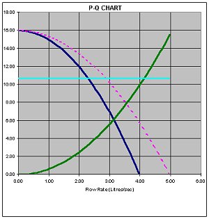 |
DC-CALC takes advantage of the charting capabilities of modern PC software and creates a chart of Pressure versus Flow Rate with both axes having a linear scale. This means that the data points form a series of smooth curves. By changing the values in the DC-CALC input cells, these curves will alter in proportion. It is much easier to interpret the Flow Rate axis when it is linear. Apart from that, it has all the benefits of the original diagram.
The Green Curve is the Die Plot, (Flow Rate through the gate versus Applied Pressure). It can be changed by altering :-
The Dark Blue Curve is the Machine Plot (Flow Rate achieved versus Pressure Available). It can be changed by altering :-
The Red Dotted Curve is the machine plot at its maximum shot speed (100%).
The Light Blue Line is the point at which maximum machine shot-end power is used. So the point where this line meets the machine plot line is the point where the machine is working at its greatest injection power.
The point where the Green Curve and the Dark Blue Curve cross is the 'Operating Point' of the die-machine combination. This determines the Flow Rate and the Pressure of this die-machine combination during the cavity filling phase.
The location of the Operating point depends largely on the alloy being cast. High density zinc alloys require more pressure to move them through the gate at an acceptable speed, so the operating point will be towards the upper left hand segment. Conversely, Al and Mg alloys require less pressure during cavity fill, but a high packing pressure after cavity fill. With regular use of DC-CALC you will gain a familiarity with the curves. Operating points at the left hand extreme represent flow restrictions and high pressure losses. If they are to the right hand extreme it indicates large gate areas, high flow rates and low pressure conditions. Operating points close to the maximum machine power indicate a good match between the die and machine's shot-end power.
The P-Q Chart gives a quick visual view of the operating condition of the die-machine combination, and is a useful tool in the die design process.
The Surface Quality Analysis section at the end of the Feasibility worksheet has been developed using data from zinc Die Cast parts, where surface quality is often more critical. However it can also be used as a guide for Aluminium.
The Chart plots Die Temperature along the X-axis.
The Y-axis plots Percent Coldflow, which is the percentage of the total casting surface area which will contain visible cold flow effects.
The two horizontal lines are the Lower Die Temperature (in blue) and the Upper Die Temperature (in red) which are calculated depending on the alloy chosen, and display at the top of the chart. These two lines give a good indication of the range of temperatures and Coldflow effects you might expect to find in practice. It will also show you how critical the die temperature will be for this particular die-machine comination.
As with many of the outputs from DC-CALC, it is not so much the absolute value of the parameter, but its relationship to other variables which is useful to know.
|